 Link is copied
TNA Connect I/O
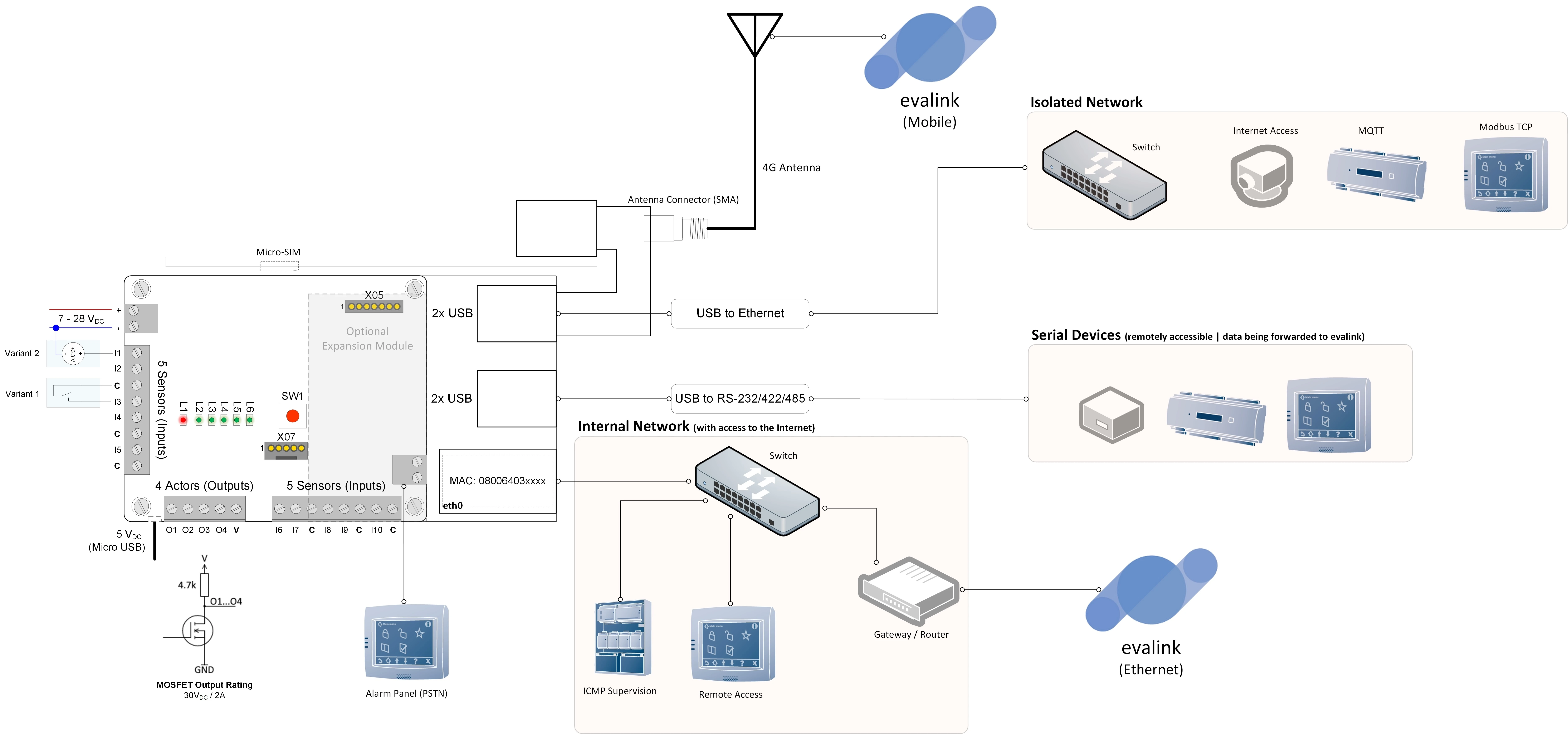
LAN
Connect the Ethernet port to the network using a shielded cable.
Antenna
Mount the antenna in a suitable location with good reception and connect the antenna cable to the SMA connector. evalink talos user interface and TNA Web Server display information about the signal strength.
SIM-Card
Insert the Micro-SIM card into the slot on the back of the modem adapter.
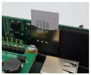
Ensure that the SIM card does not have any active PIN code. If necessary, deactivate it using a mobile phone.
Power supply
TNA Connect has two power input capabilities:
-
7 - 28VDC on screw terminal VIN
-
5V on the USB port of the Raspberry Pi
Inputs
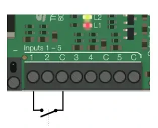
Connect the potential-free contact to the input and the common loop power (C) terminals.
Loop open: > 50kΩ
Loop closed: < 300Ω
Do NOT connect any voltage to the C terminals!
The internal loop voltage (terminals C) is connected to the potential of the power supply.
The cable length must not exceed 100m and shielding is recommended.
Outputs

The open-drain outputs work with a common external power supply of Vmax = 30V
Output in the active state is connected to GND (Ron max = 0.1 Ω)
If TNA Connect is powered off or the output is in the inactive state, the voltage is on the level of the external power V.
USB connectors for add-ons
TNA Connect has 4 USB ports for connecting optional adapters such as:
-
A Modem that acts as a backup path to evalink talos
-
A Wi-Fi adapter that acts as a backup path to evalink talos or for Hotspot functionality
-
An Ethernet network adapter for remote access to connected systems or for alarm transmission based on various protocols (e.g. MQTT, Modbus TCP)
Serial interface
TNA Connect has an RS-232 serial interface that could be used for:
-
Remote access to a connected system
-
Alarm transmission (e.g. ESPA 4.4.4, Serial Forwarding)
Dial Converter Module
TNA Connect supports the connection of a dial converter module. This makes it possible to connect older alarm systems with analog dialers.
Contact ID and SIA protocols are supported.
Connect the terminals of the dial converter module to the analog port of the alarm panel.