 Link is copied
ipTNA4i I/O

The term panel indicates any third-party alarm panel that you connect to a TNA.
LAN
Connect the Ethernet port (marked with a serial number and MAC address) to the network using a shielded cable.
Antenna
Mount the antenna in a suitable location with sufficient reception and connect the antenna cable to the SMA connector. evalink talos user interface and TNA Web Server display information about the signal strength.
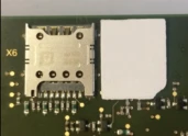
SIM-Card
Insert the Micro-SIM into the tray on the back of the ipTNA4i.
Ensure that the SIM card does not have any active PIN code. If necessary, deactivate it using a mobile phone.
Power supply
ipTNA4i has two power inputs, which are monitored independently.
Connect at least one of the two terminals X4 or X5 with a DC voltage source (10-36 VDC).
The negative terminals are interconnected as well as connected to the ground of ipTNA4i.
Inputs
Connect the desired inputs in one of the following ways:
| Input Option 1 | Unmonitored loop for use with potential-free contact. Loops open > 50 kΩ Loops closed < 300 Ω |
| Input Option 2 | Monitored loop for use with potential-free contact. The resistance of the loop itself must be < 300 Ω The loop supervision (to be activated on the TNA Web Server or on evalink talos) can detect tamper events (short circuit / open loop). |
| Input Option 3 | Apply external voltage. |
Do NOT connect any voltage to the C terminals!
The internal loop voltage (terminals C) is pulsed and connected to the potential of the power supply.
The cable length must not exceed 100m, screening is recommended.
Outputs (Actors)
Actors are relays mounted on the ipTNA4i. They are usually connected to alarm panels to notify about alarm transmission statuses (e.g. if an alarm is confirmed, if an alarm cannot be sent, etc.).
| Remote Control | - | When an actor is configured as Remote Control, it is not affected by TNA operation or alarm transmission. It can be manually triggered by a user. | A user sends a command to open or close the relay from evalink talos or using the TNA Web Server. Terminals a - b: The relay closes when “true” or “1” is selected. The relay opens when “false” or “0” is selected. |
| Uncritical Fault | Open | This actor is activated when a fault occurs but the TNA is still able to operate and send alarms. | This is due to one of the following reasons:
|
| Critical Fault | Closed | This actor is activated when a critical fault occurs on the TNA and it is not able to send alarms. Note: This functionality can only be configured on Actor #3 because of hardware differences for the critical fault actor. | This is due to one of the following reasons:
|
| Local Alarm | Open | This actor is activated if an alarm is not acknowledged by evalink talos after 20 seconds1. It is deactivated after receiving acknowledgment from evalink talos. | An alarm is not acknowledged after 20 seconds. Terminals a - b: The relay opens in the event of a failure. |
| Positive Acknowledge | Open | This actor is activated for 2 seconds in response to each sensor activation. It serves as an acknowledge machine for sensors – it indicates the sensor change has been detected by the TNA. | The relay is switched for 2 seconds Terminals a - b connected (idle) Terminals a - c connected 2 Seconds delay Terminals a - b connected |
| Negative Acknowledge | Open | This actor is activated for 2 seconds if an alarm is not acknowledged by evalink talos after 100 seconds. If there is no connection available but an alarm is generated, the actor is activated without delay and repetitions are not performed. All generated alarms are handled by Negative Acknowledge actor separately. This means that 100 seconds delay is tracked for each alarm and an indication is triggered (if necessary) for each alarm separately. |
|
1 With configurable delay time. The actor only switches to fault when the cause still persists after the delay time has expired.
For the critical fault output, there is one more configuration option on the TNA Web Server.
It is activated in case of sudden TNA power off or planned reboot. However this logic may be unwanted during a firmware upgrade.

By default, the critical fault is not activated during a TNA reboot caused by a firmware upgrade.
Delays
In some cases, it is not necessary to activate the actors immediately.
| Local alarm | 0 seconds | If an alarm is not acknowledged within this delay, the actor is activated. |
| Critical fault | 10 seconds | If the issue is not resolved within this delay, the actor is activated. |
| Ethernet disturbance | 10 seconds | If the connection is not established within this delay, uncritical and critical fault outputs are activated. |
| Mobile disturbance | 10 seconds | If the connection is not established within this delay, uncritical and critical fault outputs are activated. |
USB connectors for add-ons
ipTNA4i has 3 USB ports for connecting optional adapters such as:
-
A Wi-Fi adapter that acts as a backup path to evalink talos or for Hotspot functionality
-
An RS-232 serial interface that could be used for remote access to a connected system or for alarm transmission (e.g. ESPA 4.4.4, Serial Forwarding)
Dial Converter Module (PSTN to IP)
ipTNA4i supports the connection of a dial converter module. This makes it possible to connect older alarm systems with analog dialers.
Contact ID and SIA protocols are supported.
Connect the terminals of the dial converter module to the analog port of the alarm panel.