 Link is copied
Sensors
Sensors, also called Inputs, are used to get information about the state of connected alarming systems or about the state of the TNA itself. The change of the state of a sensor usually means there is a change of the alarm state for some connected device.
Every TNA device has 10 Inputs for sensor connections. ipTNA4i devices can support 10 additional sensors using the I/O Module.
ipTNA4i has 2 Power Sensors to monitor TNA power supplies and a Cover Contact sensor to check the box cover status.
TNA Connect V2 devices have 1 Power Sensor, while TNA Connect V1 devices operate without Power Sensors.
Physical States
A TNA periodically checks the voltage of each input and gets their physical states. The physical state is then converted to an alarming state according to the following configurations:
ipTNA4i
Enabled Loop Supervision
| 0.000V | 1.464V | Open Circuit |
| 1.465V | 2.068V | Open |
| 2.069V | 3.710V | Open Circuit |
| 3.711V | 4.168V | Closed |
| 4.169V | 4.800V | Short Circuit |
Disabled Loop Supervision
| 0.000V | 3.155V | Open |
| 3.155V | 4.800V | Closed |
TNA Connect
| 0.000V | 1.800V | Open |
| 1.801V | 3.300V | Closed |
Extension Module
The additional inputs work in the same way as the ones on ipTNA4i board but the voltage thresholds are different.
Enabled Loop Supervision
| 0.000V | 2.698V | Open Circuit |
| 2.699V | 3.046V | Open |
| 3.047V | 3.673V | Open Circuit |
| 3.674V | 3.786V | Closed |
| 3.787V | 6.670V | Short Circuit |
Disabled Loop Supervision
| 0.000V | 3.673V | Open |
| 3.674V | 6.670V | Closed |
Configure Inputs
Access level 3 or above is required to configure inputs.
To configure inputs, do the following:
- On the TNA Web Server, navigate to Alarming >
 Sensors
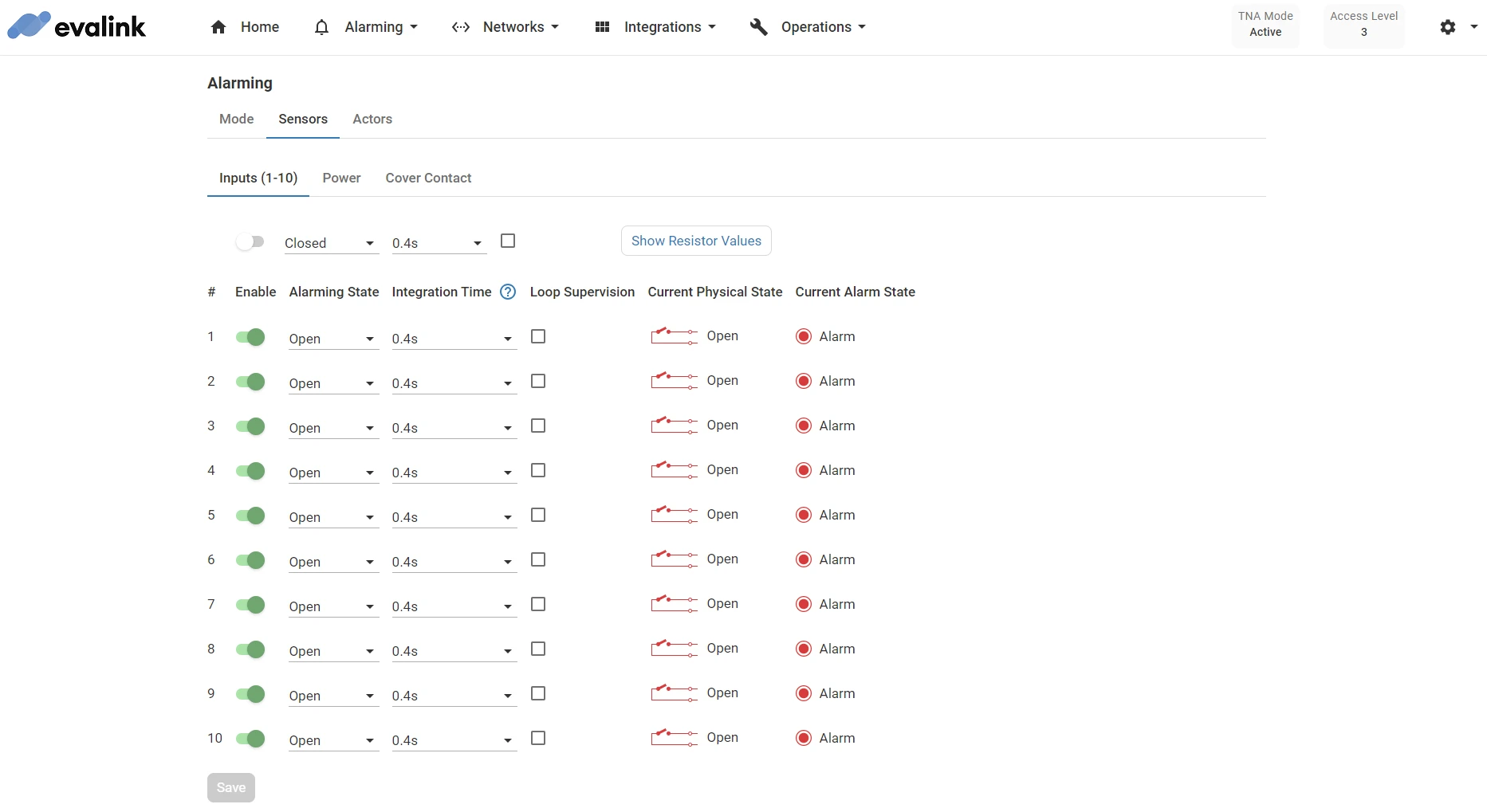
- On the Inputs (1-10) tab, configure the following parameters for each input:
| Enable | Toggle to enable or disable the input. If the input is disabled, the TNA will not check its state and therefore will not report any alarms related to this input to evalink talos. | ||||||||||||||||||||||||
| Alarming State | The alarming state could be set to 2 different values: Open or Closed.
If the physical state is either Open Circuit or Short Circuit then Tamper is reported to evalink talos, regardless of the current alarming state.
Note: When returning from a tamper state (Open Circuit or Short Circuit) to a normal state, Tamper Restore is reported to evalink talos. | ||||||||||||||||||||||||
| Integration Time | This parameter prevents the input physical state value from changing immediately after a voltage change. The sensor stays in this physical state for certain amount of time. Default value: 0.4 seconds Possible values: 0.4s, 1s, 2s, 4s, 10s, 20s, 30s | ||||||||||||||||||||||||
| Loop Supervision | This parameter is used to enable or disable Loop Supervision. When enabled, the TNA does check for Open Circuit and Short Circuit. Note: Loop Supervision is available only for ipTNA4i and the extension module. To ensure correct operation, connect your panel as follows: 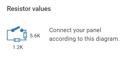 |
-
Click on Save
-
(Optional) If you need to apply the same configuration for all inputs at once, choose the parameters from the top near Show Resistor Values button then click on Save
-
(Optional) Click on Undo changes to reset the parameters to their previous values
To view or modify the current configuration for inputs from evalink talos, do the following:
-
On your evalink talos account, go to Sites > [site] > Receivers > tab
-
Click on Remote Control at the bottom of the tab
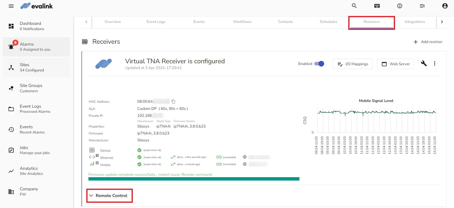
- Under Input Components, you can view the Input Mode and Input Physical State for each of the 10 inputs
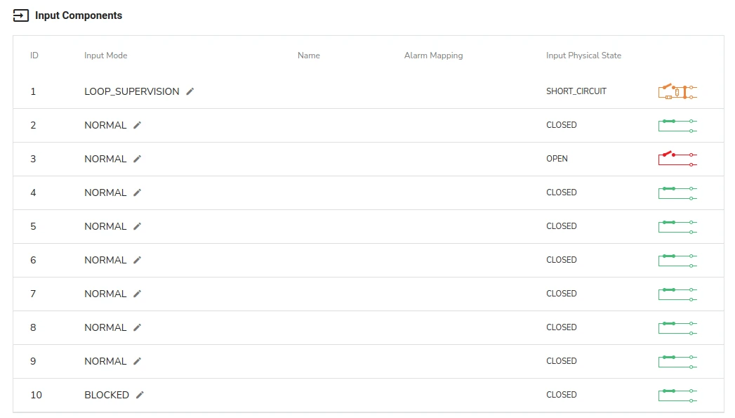
When an input is disabled from the Web Server, its Input Mode is BLOCKED as shown for input 10.
- To change the loop supervision for an input, click on next to its Input Mode and choose LOOP_SUPERVISION to enable loop supervision or Normal to disable it
Configure Power Sensors
Power Sensors functionality is available for TNA Connect V2 and ipTNA4i devices only.
TNA Connect V2 has one DC power input, ipTNA4i has two DC power inputs. The power sensors in both devices work in the same way. TNA devices can measure voltage on the power inputs and report the state change to evalink talos.
| 0.0V | 1.5V | No Power | Alarm |
| 1.5V | 7.0V | Low Power | Alarm |
| 7.0V | 15.0V | OK | Restore |
After a voltage change, the TNA will not change the state immediately. An integration time is defined for both alarm and restore scenarios:
| Alarm → Restore | 60 seconds |
| Restore → Alarm | 400 milliseconds |
To configure power inputs, do the following:
-
On the TNA Web Server, navigate to Alarming >
Sensors -
Click on Power
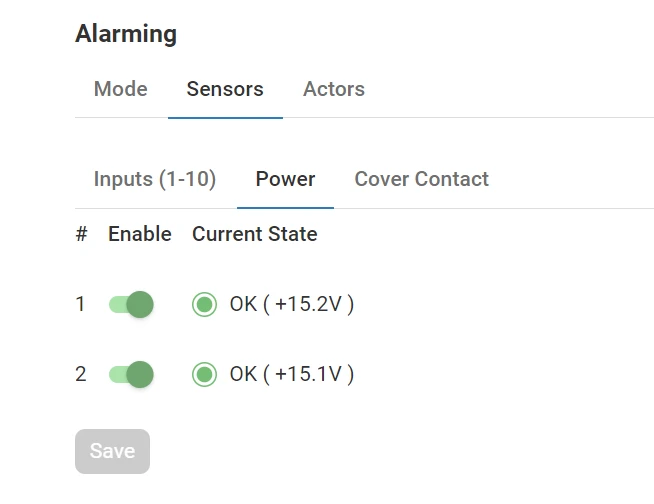
-
Toggle to enable or disable alarm reporting for each power sensor
-
Click on Save
-
(Optional) Click on Undo changes to reset the parameters to their previous values
To view or modify the current configuration for the power sensors from evalink talos, do the following:
-
On your evalink talos account, go to Sites > [site] > Receivers > tab
-
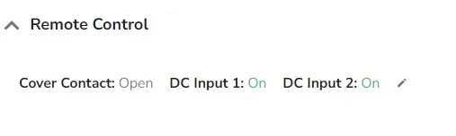
Click on Remote Control at the bottom of the tab
- Under Remote Control, you can view the state for each power sensor named DC Input 1 and DC Input 2
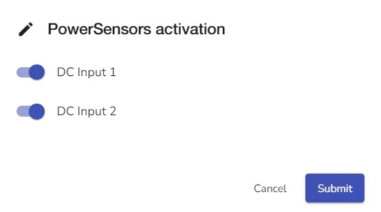
- To enable or disable the alarm reporting for each power sensor, click on next to DC Input 2 and toggle to enable or disable the alarming reporting for each power sensor then click Submit
Configure the Cover Contact
Cover Contact is available on ipTNA4i devices only.
ipTNA4i devices have an additional sensor that indicates the state of the device's box cover. When this cover is pulled off, the sensor triggers an alarm.
| Present | Closed | Restore |
| Absent | Open | Alarm |
To configure the cover contact, do the following:
-
On the TNA Web Server, navigate to Alarming >
Sensors -
Click on Cover Contact
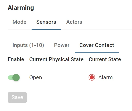
-
Toggle to enable or disable alarm reporting for the cover contact sensor
-
Click on Save
-
(Optional) Click on Undo changes to reset the parameter to its previous value