 Link is copied
TNA Connect Hardware
This article provides step-by-step instructions to identify and resolve common issues with your TNA Connect device. Follow the troubleshooting sections below based on the observed problem. Should the problem remain unresolved, please create a ticket to our support team using the evalink helpdesk.
TNA Connect V2
The TNA Does Not Power On
If the TNA does not power on, the issue may be related either to the power supply, the connector, or the power input.
For more information about device specifications, refer to the TNA Connect V2 Data Sheet.
- Power input: 7 - 36VDC on screw terminal VIN
Proceed with the following steps to resolve the potential issues:
- Verify that the DC input provides the required voltage and amperage
- Check that all wires are correctly connected and functioning
- Test the power supply
Inputs Not Responding
If inputs do not respond, possible causes include inactive site configuration, incorrect wiring, or a voltage applied to Common (C).
Do not apply voltage to Common (C) terminals. Doing so will cause permanent damage to the device and is not covered under warranty.
Make sure to choose appropriate sized wires, since large diameter wires may fail to connect.
For more information about inputs, refer to the Inputs section.
Proceed with the following steps to resolve the potential issues:
-
Test the inputs:
- Loop Input 1 (I1) to its Common (C)
- Log in to your evalink talos account
- (evalink talos) Navigate to Site → Overview and click on Change
OR - (evalink Installer Portal) Select the Site and click Configure
- (evalink talos) Navigate to Site → Overview and click on Change
- Verify the site is active (activate it if not)
- Under Receivers → Remote Control, check the input response
-
Repeat the test for the other inputs
-
Replace the wires with tested working ones
Outputs Not Responding
Outputs can be tested by wiring an output to an input.
Make sure to choose appropriate sized wires, since large diameter wires may fail to connect.
For more information about outputs, refer to the Outputs section.
Proceed with the following steps to resolve the potential issues:
- Log in to your evalink talos account
- (evalink talos) Navigate to the relevant Site and click on Receivers
OR - (evalink Installer Portal) Select the Site, click Configure then navigate to the Receivers tab
- (evalink talos) Navigate to the relevant Site and click on Receivers
- Open the Web Server
- On the Web Server, enter the required passwords to reach Access Level 4
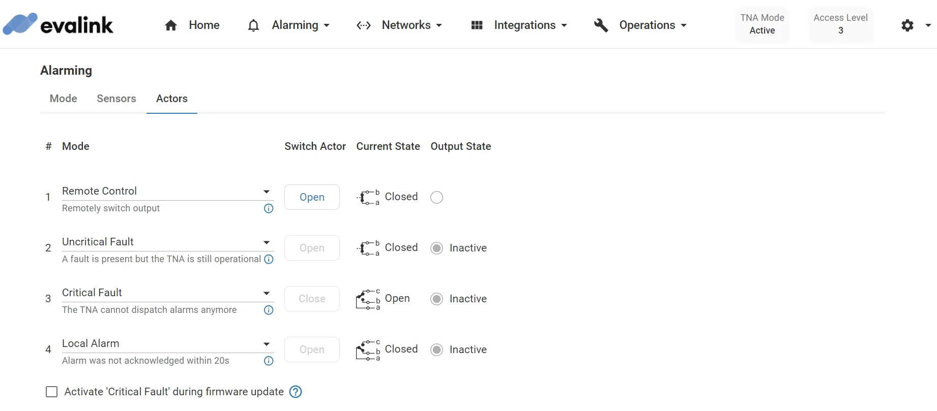
- Go to Alarming → Actors
- Ensure Output 1 is set to Remote Control
- Connect:
- The wire from Input 1 (I1) to the desired output
- The wire from the output to Input 1 Common (C)
- Use Switch Actor to trigger the output
- In evalink talos, select Events and confirm the alarm was triggered
- If the alarm is triggered, the output works (the issue may be related to the alarm panel wiring).
- If not, replace the wires and test again.
Note: Reset the settings after testing. By default, output settings should look like the image below:
TNA Connect V1
The TNA Does Not Power On
If the TNA does not power on, the issue may be related either to the power supply, the connector, or the power input.
For more information about device specifications, refer to the TNA Connect Data Sheet.
- Power input options:
- 7 - 28VDC on screw terminal VIN
- 5V on the USB port of the Raspberry Pi
Proceed with the following steps to resolve the potential issues:
- Verify that the DC input provides the required voltage and amperage
- Use the USB port instead of the screw terminal VIN and test again
- Check that all wires are correctly connected and functioning
- Test the power supply
Inputs Not Responding
If inputs do not respond, possible causes include inactive site configuration, incorrect wiring, or a voltage applied to Common (C).
Do not apply voltage to Common (C) terminals. Doing so will cause permanent damage to the device and is not covered under warranty.
Make sure to choose appropriate sized wires, since large diameter wires may fail to connect.
For more information about inputs, refer to the Inputs section.
Proceed with the following steps to resolve the potential issues:
-
Test the inputs:
- Loop Input 1 (I1) to its Common (C)
- Log in to your evalink talos account
- (evalink talos) Navigate to Site → Overview and click on Change
OR - (evalink Installer Portal) Select the Site and click Configure
- (evalink talos) Navigate to Site → Overview and click on Change
- Verify the site is active (activate it if not)
- Under Receivers → Remote Control, check the input response
-
Repeat the test for the other inputs
-
Replace the wires with tested working ones
Outputs Not Responding
Outputs can be tested by wiring an output to an input.
Make sure to choose appropriate sized wires, since large diameter wires may fail to connect.
For more information about outputs, refer to the Outputs section.
Proceed with the following steps to resolve the potential issues:
- Log in to your evalink talos account
- (evalink talos) Navigate to the relevant Site and click on Receivers
OR - (evalink Installer Portal) Select the Site, click Configure then navigate to the Receivers tab
- (evalink talos) Navigate to the relevant Site and click on Receivers
- Open the Web Server
- On the Web Server, enter the required passwords to reach Access Level 4
- Go to Alarming → Actors
- Ensure Output 1 is set to Remote Control
- Connect:
- The wire from Input 1 (I1) to terminal 01b of Output 1
- The wire from Common (C) to terminal 01a of Output 1
- Use Switch Actor to trigger the output
- In evalink talos, select Events and confirm the alarm was triggered
- If the alarm is triggered, the output works (the issue may be related to the alarm panel wiring).
- If not, replace the wires and test again.
Note: Reset the settings after testing. By default, output settings should look like the image below: