Virtual Receiver Integrations Overview
Definitions and Basics
In this documentation:
-
an alarm transmitter is a hardware device that sends alarms to evalink talos
In the most typical case, the device is an alarm panel.
-
an alarm transmitter integration, as opposed to other evalink talos integrations, is an integration in which evalink talos itself monitors the connection with the connected alarm transmitter device (see section Connection Monitoring Reference)
From the implementation point of view, an alarm transmitter integration is an abstraction for the appropriate virtual receiver on evalink talos side. For example, the Ajax, Jablotron, and Risco panels interact with evalink talos via the Virtual DC09 Receiver.
A virtual receiver is responsible for:
-
monitoring the connection with the transmitter
-
receiving alarms from the transmitter via the appropriate protocol – for example, via the SIA DC-09 protocol
evalink talos supports a number of industry-accepted protocols: SIA DC-09, VdS 2465 / VdS SecurIP, FlexC, Sur-Gard, Paradox, etc.
-
evalink talos integrations for which connection monitoring is performed by a third party (for example, the Alarm.com integration) are not considered alarm transmitter integrations.
Virtual Receivers
For the full list of virtual receivers and integrations powered by them, see section evalink talos Virtual Receivers.
The Company > Integrations page in evalink talos UI actually lists not alarm transmitter integrations themselves, but the appropriate vitrual receivers. In most cases, you can identify a virtual receiver by the word Receiver in the integration name – for example, Virtual TNA Receiver.
Note that Generic Surgard Receiver, Farwest IP Receiver, and Fawest VoIP Receiver are not marked as virtual, but are alarm trasmitter integrations nevertheless.
Despite their names, Virtual SMS Receiver and Virtual Email Receiver are not considered alarm transmitter integrations, since no hardware devices and no connection monitoring are involved in these integrations.
The Alarm Transmitter Term
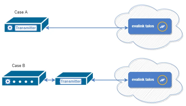
The term alarm transmitter may denote (see the figure below):
- an alarm panel with a built-in transmitter – a device that both produces alarms and transmits them to the alarm management system
OR - a group of devices
- an alarm panel that produces alarms
- a dedicated transmitter connected to it that transmits the alarms – for example, a Sitasys TNA device
From evalink talos perspective, there's no substantial difference between these two cases.

Virtual Receiver Global Settings
You can configure several global settings that will be available for all virtual receivers in your tenant.
Admin and Manager users can access Virtual Receiver Global Settings by navigating to Company > Settings > Receivers.
The following settings are available globally:
- SLAs
SLAs or Service Level Agreements, define how virtual receivers connect to evalink talos.
In this setting area, you can view the list of your custom SLAs and add new ones. For details, see section Configure a Custom SLA Scheme.
- Virtual Device Types
Virtual Device Types are labels that allow you to better differentiate between multiple virtual receivers. This is especially helpful when you work with many sites and virtual receivers in your company.
Adding a New Virtual Device Type
To add a new Virtual Device Type:
-
Navigate to Company > Settings > Receivers
-
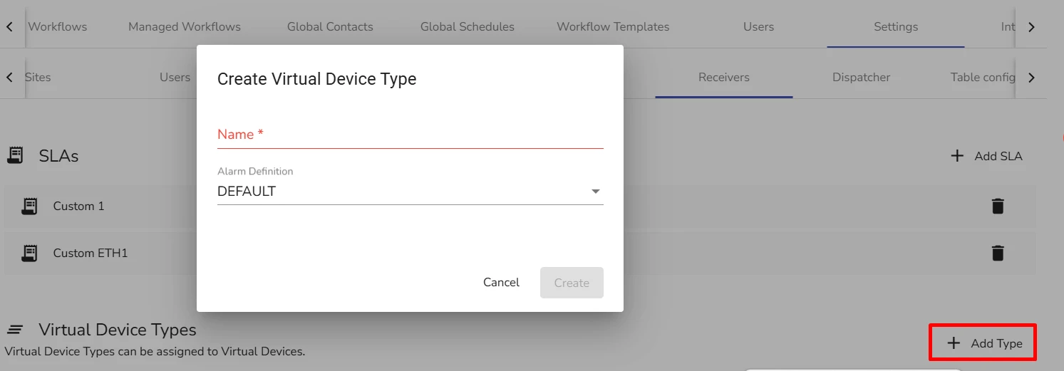
In the Virtual Device Types area, click Add Type
The Create Virtual Device Type dialog opens.

-
In the Name field, specify the Virtual Device Type name
-
From the Alarm Definition dropdown, select the alarm definition system for this type.
Once you have created a Virtual Device Type, it becomes available for selection when you configure Device Information for any Virtual Receiver Record on all sites in your company.
Connect an Alarm Transmitter to evalink talos
To start working with a transmitter, it is necessary to:
-
enable the appropriate Virtual Receiver and configure the global settings for it on the Company > Integrations page. Only Administrator has the permissions to do so
To know which Virtual Receiver is needed for a particular integration, see section evalink talos Virtual Receivers.
-
connect the transmitter to the Virtual Receiver instance that is created on the Integrations tab of a particular site. This operation can be performed by Administrator or Manager
The instructions in this section describe the generic flow. The exact configuration and connection procedures for various Virtual Receiver types are described in the dedicated sections of each virtual receiver.
By default, all Virtual Receivers are disabled.
When a Virtual Receiver is disabled globally, site-level Virtual Receiver records for this integration are not accessible, which means that:
-
no new Virtual Receiver instances can be created – therefore, no new transmitters that rely on the integration can be connected to evalink talos
-
if the integration was enabled previously, and some transmitters were already connected, these transmitters
- stop receiving alarms
- have their Virtual Receiver instances hidden from the Sites > [site] > Integrations page
Only Administrator can enable or disable an integration globally. Manager and Operator can only view the global Virtual Receiver status.
After a transmitter is connected to a site, the Virtual Receiver instance record on the [site] > Integrations page displays the details and the status of the transmitter that was connected. Multiple Virtual Receiver instances may be displayed on the [site] > Integrations page.
The transmitter record displays the key integration details and the visualization of the device connection status, see section View Connection Status Indicators on the Virtual Receiver Page in this article.
View Connection Status Indicators on the Virtual Receiver Page
To access the virtual receiver page, go to the site Integrations tab (Sites > [site] > Integrations) and click on the corresponding virtual receiver subtab – for example, FlexC Receiver.
The record of the connected transmmitter on the virtual receiver page displays the following details:
-
the key parameters of the transmitter
The parameters are integration-specific: MAC address for a TNA device, account details for FlexC, etc.
-
the connection status of the transmitter
The connection status indications are explained below.
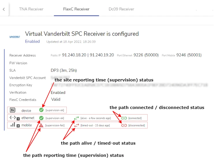
A typical transmitter record is shown on the figure below.

A separate line of connection status indicators is shown for:
- device – the overall transmitter status / site status
- each transmission path separately
- ethernet – the primary path
- mobile – the secondary path
For a definition of a transmission path in general, and of the primary / secondary transmission paths, see section Direct Monitoring Scheme Overview > Transmission Paths.
The following indicators are available:
-
the site reporting time (supervision) status icon for device – indicates the overall connection status of the transmitter
-
status indicates that the transmitter is connected
-
status indicates that the site reporting time control interval was exceeded and a site failure alarm (CID 350 or its analog) was sent
For details on the site reporting time control interval, see section Connection Monitoring Overview > Site Reporting Time in section Connection Monitoring Reference.
-
-
(optional) the path reporting time (supervision) status icons for ethernet and mobile transmission paths – display the connection status of the primary path and of the secondary path, accordingly
-
the path reporting time (supervision) status icons for a path / show the status of the path reporting time control interval
For details on path reporting time, see section Direct Monitoring Scheme Overview > Path Reporting Time in section Connection Monitoring Reference > Direct Connection Monitoring (SLA).
A red icon indicates that path reporting time was exceeded and the appropriate alarm (CID 351 or 352) was sent.
-
the alive / timed-out status icons / icons show the status of the the poll timeout control interval
For information about poll timeout, see section Direct Monitoring Scheme Overview > Poll Timeout in section Connection Monitoring Reference > Direct Connection Monitoring (SLA).
A gray icon indicates that poll timeout was exceeded. This status indication is purely informational and doesn't signal a connection issue yet.
-
the connected / disconnected status icons / icons display the TCP connection status
These statuses are displayed only for the virtual receivers that communicate over TCP and are configured to have a permanent TCP connection with the transmitter.
For information on the connection protocols used by various virtual receivers, see section evalink talos Virtual Receivers. A virtual receiver that communicates over TCP can be configured to use a permanent or an on-demand connection. The connection type is chosen during the virtual receiver setup according to user preferences.
A gray icon indicates that the transmitter is disconnected. This status indication is purely informational and doesn't signal a connection issue yet.
info1. The ethernet and mobile transmission path names reflect the most typical configuration. In the real practice, any configuration is possible – for example, a single-path transmitter can use GPRS / mobile transmission path, or both the primary and the secondary transmission paths can be Ethernet paths. evalink talos UI will always display the primary path as the ethernet one and the secondary path as the mobile one.
2. For virtual receivers that use indirect connection monitoring scheme and have no concept of transmission paths, visualization differs:
- for Frontel GI Virtual Receiver, the Server Connection and Panel Connection statuses with similar icons / and / are displayed
- for Sur-Gard based virtual receivers (Generic Sur-Gard Receiver, Farwest IP Receiver and Farwest VoIP Receiver), a completely different connection status indication is used. This indication will be described in the next documentation releases
For details on indirect connection monitoring scheme, see section Connection Monitoring Overview > Indirect Connection Monitoring in section Connection Monitoring Reference. -
Add Device Information to a Virtual Receiver Record
If you have multiple receiver connections, it's useful to add readable descriptions to receiver instances if you want to easily differentiate between them.
For example, if you work with multiple Ajax panels in your tenant, you can create AJAX Virtual Device
Type. You can specify Ajax-specific event definition for this type. This way, evalink talos will parse alarms
which come from devices with this device type using the Ajax event definition and not the default SIA DC09 one.
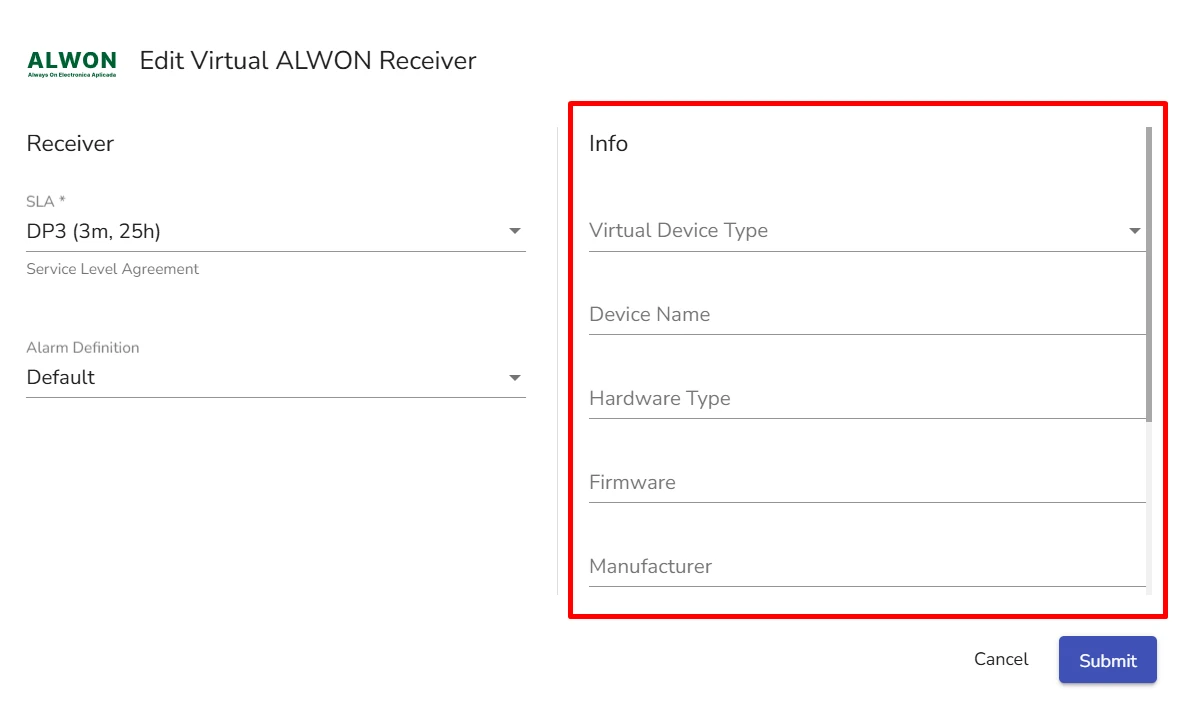
You can populate description fields once you open a Virtual Receiver creation / editing dialog.

To add device information:
-
(Optional) Specify the following for a particular instance of Virtual SIA DC09 Receiver:
- Virtual Device Type
- Device Name
- Hardware Type
- Firmware
- Manufacturer
- SIP Username
- SIP Password
-
(Optional) In the Comment field, add a freeform comment to the receiver instance
-
Click Submit
 Link is copied