Generic Receiver Global Setup
In this section, the term panel indicates a hardware alarm panel of any model, if not stated otherwise.
The term a receiver instance indicates a single Generic Receiver with a unique receiver account assigned by an evalink talos user who configures it for a particular site.
As it is with other virtual receivers, you must first enable Generic Receiver on a global level. After that it is possible to enable and configure instances of Generic Receiver for particular sites.
When Generic Receiver is configured globally, it becomes available for configuration in the Receivers tab of all sites. If you disable Generic Receiver globally, all receiver instance records will be removed from the Receivers tab of each site and it will no longer be available for configuration on the site level.
Enable Generic Receiver Globally
To enable Generic Receiver on a global level:
-
Go to Company > Integrations
-
Scroll to the Generic Receiver and click Add Integration
The configuration dialog opens. The toggle is set to Integration Enabled automatically.
-
Click Submit
Add A Connector to Generic Receiver
To actually be able to work with the Generic Receiver, you need to add at least one connector to it. Connectors can be configured to use various supported protocols and configurations. Each particular instance of a Generic Receiver on a site uses one connector.
Once you add a connector, you are able to use it when configuring an instance of Generic Receiver at a site level.
To add a connector:
-
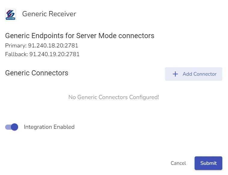
Open the global Generic Receiver configuration dialog by clicking Add Integration or Edit button, if you have already enabled Generic Receiver
-
Click Add Connector
A Connector configuration dialog opens.
-
In the Name field, type the name of the new connector.
infoIt is best practices to create a self-explanatory name for the connector so that users who work with the receiver on site level are able to quickly select the necessary connector.
-
Toggle between Client or Server modes for the connector
infoIf you select the Server mode, the Generic Receiver on evalink talos side acts as the responding network node. It listens to port 2781 for a third-party receiver to initiate the connection If you select the Client mode, it acts as the initiating network node.
The Server / Client modes do not impact how data is exchanged between evalink talos Generic Receiver and third-party receivers, only how the connection is established.
-
(Optional) Check Global Connector checkbox if you want evalink talos to include this connector in the 'Global Connectors' list
infoA single instance of a Generic Receiver on an evalink talos site only connects to a single connector. Sometimes, it is necessary to receive alarms from multiple connectors to a single Generic Receiver instance. For this case, it is possible to use Global Connectors from the list.
When working with the 'Global Connectors' list, Generic Receiver looks up for alarms with a matching account ID among all the connectors in the list.
-
If you have selected Client mode, in the Primary ATP field, add the host IP and the port for the primary Alarm Transmission Protocol server and a port that server listens to
infoPopulate the fields with an IP and a port number, separated by a colon. Example:
91.240.01.01:2781. -
Configure the TLS connection
infoThis action is optional for Client mode and obligatory for Server mode. For details, see section Configure TLS details for a Generic Receiver Connector below.
-
In the Supervision field, enter the time in seconds that denotes the supervision period
-
(Optional) In the Supervision dropdown list, select a site at which evalink talos triggers supervision events
infoIf you leave this field empty, evalink talos doesn't trigger supervision events.
It is best practices to create a dedicated site for each connector to monitor the Generic Receiver's supervision.
-
If you have selected a site for Supervision Alarms, in the Monitoring Mode select one of the following:
- Connection is monitored based on exchanged messages
- Connection is monitored based on the existence of TCP connection
-
In the Polling Direction field, select between the following Polling options:
- Remote receiver sends the polling, evalink talos acknowledges
- evalink talos sends the polling, remote receiver acknowledges
-
(Optional) Add a polling message and a polling reply in the respective fields if necessary
infoBy default, the protocol you select defines the polling message and reply. You can use this step to override them.
-
(Optional) Select and configure protocol
infoFor details on protocol configuration, see section Configure Protocol Details for the Generic Receiver Connector below.
-
Configure Mapping
infoFor details on Mapping Configuration, see section Configuring Mapping for the Generic Receiver Connection below.
-
Click Submit
Configure TLS Details for a Generic Receiver Connector
TLS configuration depends on your selection of Server or Client mode for the Generic Receiver. If you select the Server mode, configuring TLS details is obligatory. If you select the Client mode, this step is optional.
To configure TLS encryption:
-
If you have selected Client Mode and want to use secure connection, select TLS option and enter PSK and PSK Identity as is described in steps 2 and 3
-
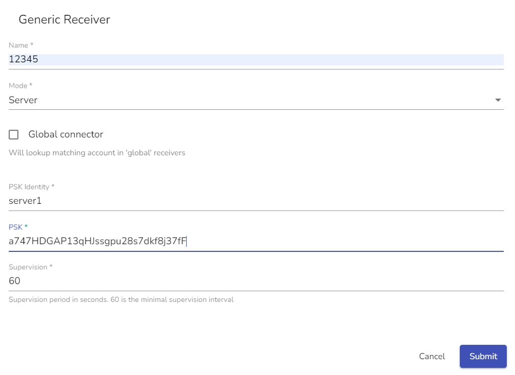
If you have selected Server mode or checked TLS option in the Client mode, in the the PSK Identity field, enter the pre-shared key identity
infoPre-shared key identity is the unique id number of the third-party device or receiver you are connecting to the evalink talos Generic Receiver via this connector. Example:
receiver1You need to create these credentials on your own. It is best practices to use a PSK generator app for a strong and secure key. -
If you have selected Server mode, in the PSK field enter the pre-shared key
infoPre-shared key is an alphanumeric sequence which acts as a password in combination with the PSK ID. Together the pair is used to authenticate access and establish encryption for the data that is exchanged between evalink talos and the third-party receiver.
In the figure below, the values for PSK and PSK identity are examples:
Configure Protocol Details for the Generic Receiver Connector
evalink talos Generic Receiver supports several connection and alarm transmission protocols. The selection of protocol defines which alarm data is transmitted and how evalink talos parses it.
To configure protocol details, you need to open the necessary connector record in Edit mode.
-
(Optional) Check the Use Advanced Sur-Gard Protocol box to be able to receive visual verification events
infoIf you enable this option, you are using a specific Sur-Gard configuration. Thus, advanced alarm message mapping options become unavailable for further manual configuration.
-
(Optional) Check the Send DC4 on connection activation option
infoDC4 stands for "Device Control 4," which is ASCII character 20 (14H)
-
In the Protocol field, select a protocol the connector will use from the dropdown list
-
(Optional) In the Leading byte field, specify the leading byte
infoLeading byte is prepended to the data packet before it is sent. It can be used for identification, sync, or be part of a protocol requirement.
By default, the protocol you select defines the Leading byte. If you use Sur-Gard, there is no Leading byte. If you use Ademco, the default Leading byte is a line-feed(byte 10).
-
(Optional) In the Trailing byte field, specify the trailing byte
infoTrailing byte is appended to the end of a data packet. It can be used for verification, termination or protocol compliance.
By default, the protocol you select defines the Trailing byte. If you use Sur-Gard, the default Trailing byte is DC4. If you use Ademco, the default Trailing byte is carriage-return(byte 13).
-
(Optional) In the Ack and Nack fields, specify how evalink talos responds to received messages:
- Ack means acknowledgement. This signal is transmitted back to the sending party to indicate the message is received and understood
- Nack means negative acknowledgement. This signal is transmitted to indicate that evalink talos can't successfully receive the message
infoThe default value for Ack is Ascii character ACK (byte 6).
The default value for Nack is Ascii character NAK (byte 21 - 15H).
Configuring Root Mapping for the Connector
Message mapping defines details about how evalink talos processes incoming data based on its structure and origin.
Mapping is useful for situations when you have a large number of connected devices and need to properly route messages coming from them.
Sur-Gard accounts usually consist of 4 or 6 digits and do not have to be unique to particular devices. If a company manages more than 10000 4-digit
device accounts, it means, some of the account IDs are repeated. When no mapping is applied, evalink talos sends an incoming alarm with the value of 9999 for the Account
to the site with corresponding Generic Receiver Account, 1000. But if there are two devices with the same account that use two different connectors, evalink talos
needs to know how to differentiate between the two and send them to their respective sites.
Using the mapping you can configure each connector that receives messages from different devices that share an account number to send them to appropriate sites. To do this,evalink talos generates a new unique account number from the message according to the mapping rules and then sends it to the site with the same unique account.
There are three mapping options:
- No Mapping: evalink talos uses the account number in the incoming alarm message 'as is'
- Root Mapping: the default global mapping rules for a specific connector
- Conditional Mapping: override the global mapping rules when a message meets certain set conditions
To configure message mapping, you need to open the connector record in Edit mode.
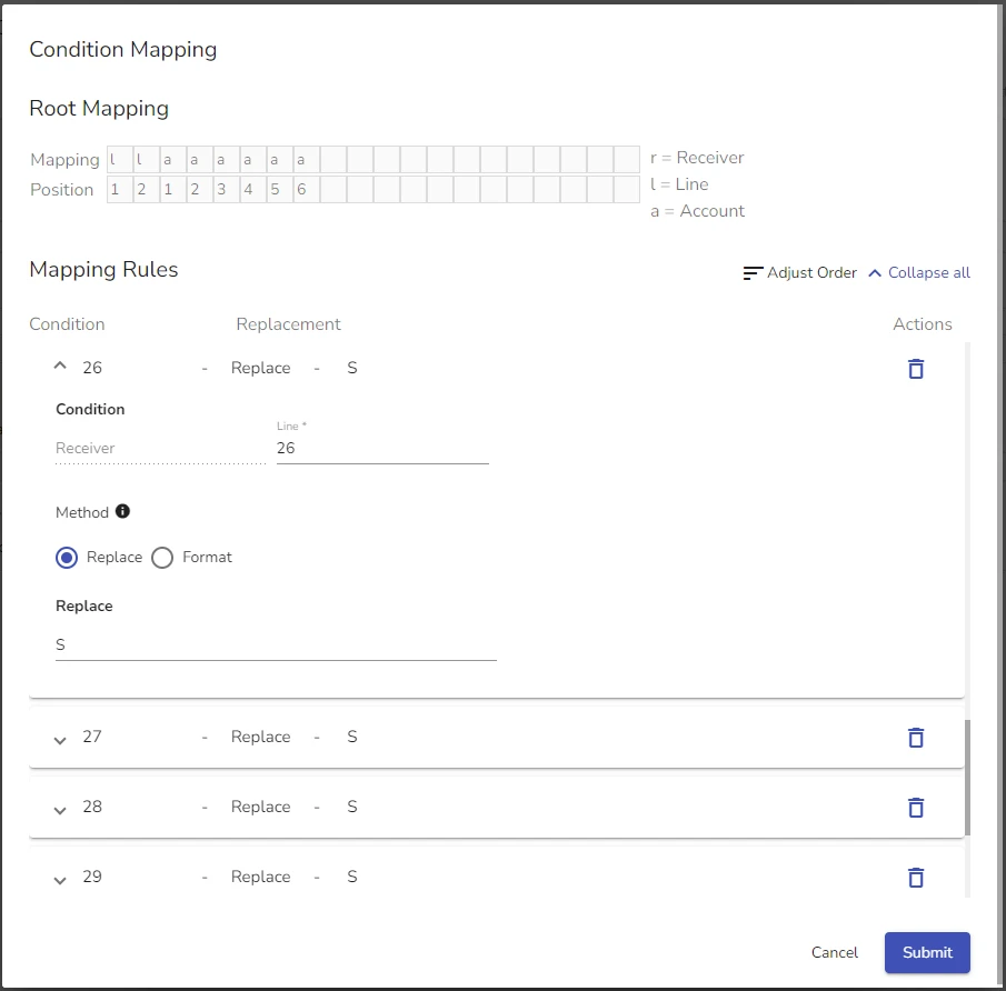
In the mapping area, the Mapping field holds specific mappings which are rules for how evalink talos must extract and interprete specific parts of the message.
You can populate the Mapping field with any alphanumeric values. However, evalink talos takes the following three values and replaces them with data from the incoming message, according to the position row:
-
rstands for Receiver: it indicates a part of the incoming message that identifies the receiver device -
lstands for Line: it indicates a part of the incoming message wich contains the line number on the third-party receiver where the message originates -
astands for Account: a device identifier that helps evalink talos place the message with a particular site. Account numbers are not unique to particular devices.
The Position field identifies where in the message specific data is located that evalink talos needs to use in the generated account.
For example, if the Account number in the original alarm message is 02655 and the positions corresponding to the a fields are 135, evalink talos
uses the numbers 065 from the original message to add to the generated account number.
The quantity of the r, l, and a values used in the mapping denote the length of the corresponding generated account parts. If you set lll in the
mapping field, it means that your line number in the generated account is 3 characters long. If the line number in the original alarm message is 4, the line number
in the generated account is 004.
For example, if you configure mapping as shown in the figure below:
If the device ID part of the incoming message looks like S011[#784019|Nri00/FR000]<DC4>, the Receiver number is 1, line number is 1 and Account number is 784019
The generated account number is LOC010014019.
In this generated account number:
LOCis the first part according to the mapping01is the Receiver number. Although in the complete message the actual receiver number is 1, but the mapping sets the length of the Receiver definition to minimum 2 digits, so a zero is added001is the Line number. The actual receiver number in the original message is 1, but the mapping sets the length of the Line definition to minimum 3 digits, so two zeros are added4019is a part taken from the original account number. The original account number has 6 digits, the mapping tells evalink talos to take only digits in the positions 3, 4, 5 and 6, which are the last four digits of784019from the original message
Add Conditional Mapping to Connector
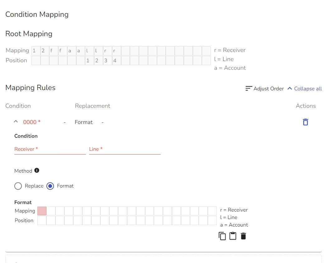
Conditional mapping allows you to override global mapping rules for a connector when a particular line and receiver match. It becomes available only if you use Line and / or Receiver values for Root mapping.
Conditional mapping allows you to replace or format the existing Root mapping using Line and / or Receiver as conditions.
-
Open the Connector record in the Generic Receiver Global configuration dialog
-
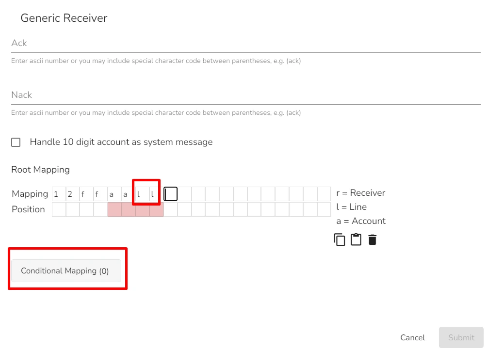
Scroll to Root Mapping and configure the Mapping and Position fields with line, receiver or both
-
Click the Conditional Mapping option
Conditional Mapping configuration dialog opens.
 info
infoIf in the Root mapping scheme you use both Line and Receiver values, you need to set conditions for both.
-
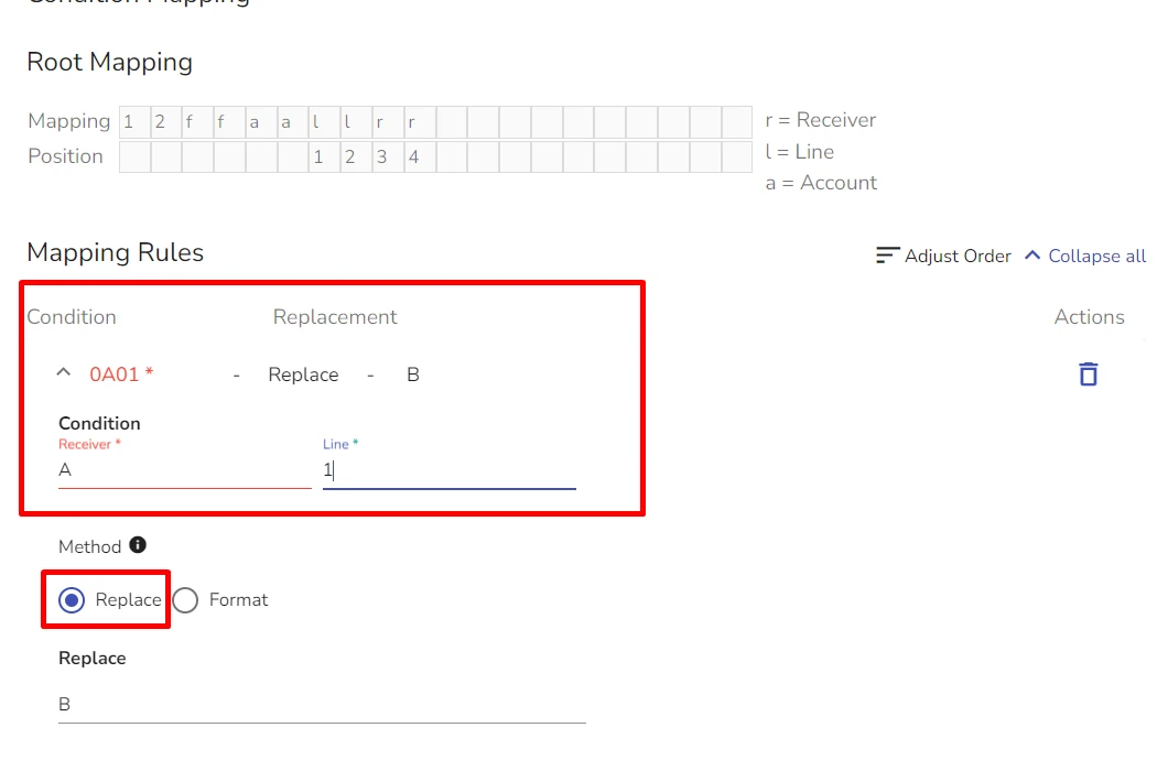
In the Condition field, specify the value for Line and / or Receiver that you want formatted or replaced
infoThe number of characters of either Line or Receiver fields should not exceed the number of l and r values used in the Root mapping.
-
Select the override method:
-
Replace option: allows you to replace existing values with new ones
Example:
-
Format option: allows you to create new mapping-position pairs for specific values in the incoming messages
-
-
Click Submit
Edit Generic Receiver on a Global Level
When editing the Generic Receiver globally, you can enable or disable it and add more Connectors.
To edit the Generic Receiver:
-
Navigate to Company > Integrations and scroll to the Generic Receiver
-
Click Edit Integration
-
In the dialog that opens, edit the necessary data, delete existing or add new Connectors
-
Click Submit
Delete Generic Receiver Globally
To delete Generic Receiver Globally:
-
Go to Company > Integrations
-
Click the corresponding three dots icon
-
Select Delete Integration
-
Type the confirmation and click Confirm Delete
If you have Generic Receiver instances connected and configured on any site, deleting the integration on the global level will remove all configured receivers and their configuration data.
 Link is copied