Virtual Frontel GI Receiver Overview
In this section and all its subsections, the term panel indicates a Resideo ® Videofied panel, if not stated otherwise.
The terms panel and alarm transmitter are synonyms.
Virtual Frontel GI Receiver Basics
Virtual Frontel GI Receiver is an entity in evalink talos that implements the Frontel GI integration.
In this section and its subsections, the term Virtual Frontel GI Receiver can also indicate a Virtual Frontel GI Receiver instance registered on a site that receives alarms from a particular panel.
Virtual Frontel GI Receiver allows connecting a wide range of Resideo ® Videofied panels, see section Supported Panel Models for some examples.
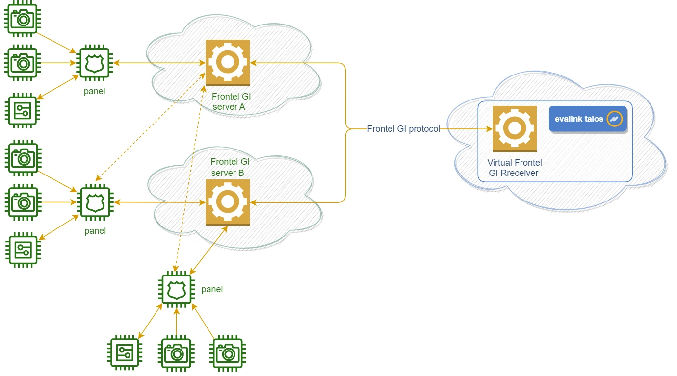
In case with Frontel GI integration, the communication between panels and evalink talos occurs through a Frontel GI server, which acts as a proxy. Virtual Frontel GI Receiver uses an indirect connection monitoring scheme, in which alarm transmitters are connected to evalink talos through an intermediate remote service, and the connection with this service is monitored in the first place. For details on this connection scheme, see section Connection Monitoring Reference > Indirect Connection Monitoring.
A Frontel GI server has a network of panels that are installed on remote customer locations and connected to it. Each panel, in its turn, has a number of devices connected, such as cameras, relays, keyfobs, etc. These devices can send data and / or trigger an alarm on the panel. Video clips and live camera views delivered in the alarm details allow to perform video verification of alarms.
A Frontel GI server forwards the alarms from all connected panels to evalink talos.
Communication between a Frontel GI server and evalink talos occurs over Frontel GI protocol – a proprietary alarm communication protocol used by Frontel GI servers.
The figure below shows the connection scheme used by the Frontel GI integration:

Several Frontel GI servers can be connected to evalink talos. There are scenarios when one of the Frontel GI servers is used as a secondary (fallback) server for the primary (main) server.
To start receiving alarms through Virtual Frontel GI Receiver, the following steps need to be performed on evalink talos side:
-
Define evalink talos sites to be used as supervision sites for Frontel GI servers (see section Server Connection Monitoring for details). It is recommended to create a dedicated supervision site for each Frontel GI server to be connected.
Sites can be created by Administrator and Manager, but can be added to the global Virtual Frontel GI Receiver configuration (see p. 2 below) by Administrator only.
-
Configure Virtual Frontel GI Receiver on the global (Company) level
This involves configuring the connection settings for all Frontel GI servers involved. These operations can be performed by Administrator only.
Some setup on the Frontel GI server side is also necessary, see section Global Integration Setup.
-
Add Virtual Frontel GI Receiver instances to all sites that will receive alarms from panels
This involves setting up the connection with the particular panels. These operations can be performed by a user with Administrator or Manager permissions after the integration is configured globally (see p. 2 above).
Each Virtual Frontel GI Receiver instance can receive alarms from one panel only. Several Virtual Frontel GI Receiver instances can exist on one site.
For details, see section Virtual Receivers Setup on the Site Level.
For each instance of Virtual Frontel GI Receiver, Virtual Receiver logs are available for download and online work. For details on working with Virtual Receiver logs, see section Working with Virtual Receiver Logs.
Connection Details
Connection between a Frontel GI Server and evalink talos
A persistent TCP connection is maintained between a Frontel GI server and evalink talos.
Frontel GI server acts as a client, and evalink talos performs the role of a server. A Frontel GI server establishes a TCP connection on one of evalink talos public IP addresses, on the dedicated evalink talos port for Frontel GI.
Interaction with the Panel
evalink talos is agnostic of any details that concern the interaction and data exchange between the panels and the Frontel GI server.
It is known that, when an alarm is triggered on a panel, the panel sends a Frontel GI protocol event (or a series of such events) to the Frontel GI server and provides the associated data (if any) for download – for example, the video clips available with the alarm.
The Frontel GI server forwards this information to evalink talos, which then interacts with the server in order to download the data associated with the alarm.
When an event is received from a panel, evalink talos:
-
triggers a corresponding alarm
-
downloads the data associated with the event from the Frontel GI server and attaches these data to the alarm
The data provided by the panel may take some time to transfer.
While the data transfer is in progress, evalink talos has access to the settings configured on the panel (the areas configured and devices connected to each area) and to live camera views. This information is displayed in the Virtual Frontel GI Receiver instance details on the respective site in evalink talos. For more information, see section Virtual Receiver Setup on the Site Level > Panel Status View.
When the data transfer is over, the panel configuration details and live camera views stop being accessible in evalink talos UI.
Connection Monitoring
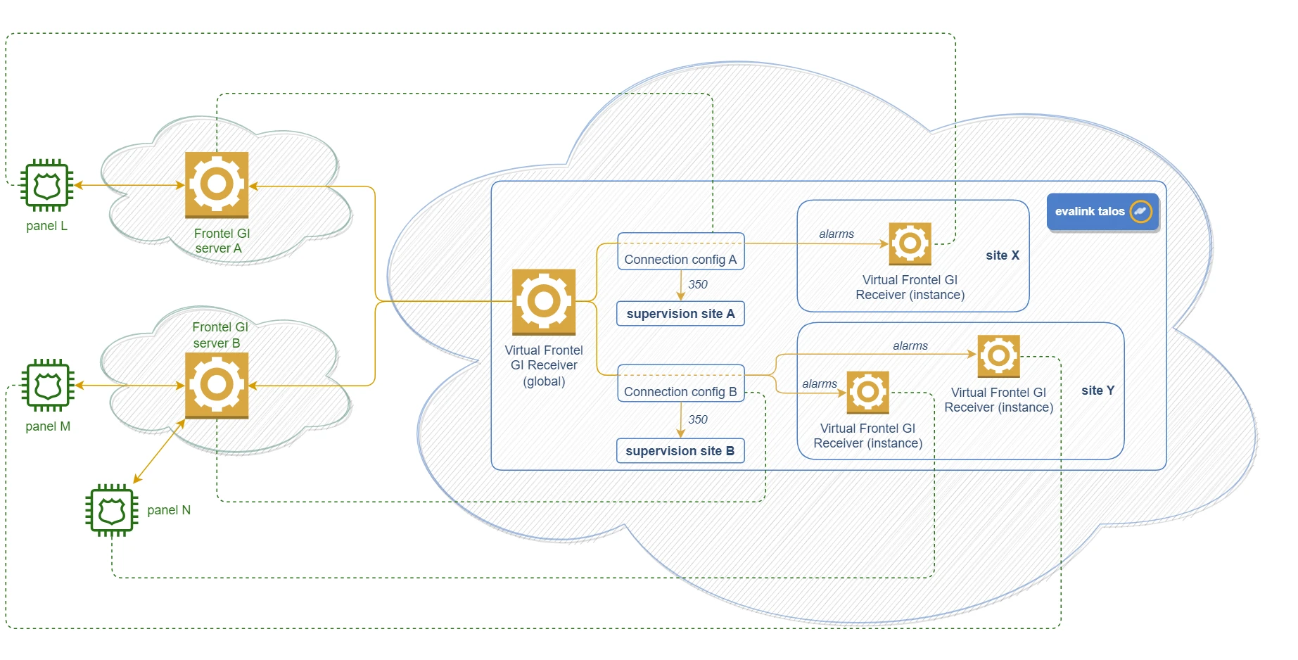
The detailed connection scheme on evalink talos side, with all types of sites involved, is shown on the figure below:

The concept of supervision sites is explained in section Supervision Sites.
Server Connection Monitoring
A Frontel GI server polls evalink talos with heartbeat events.
Virtual Frontel GI Receiver stores the timestamp of the last heartbeat event received from each Frontel GI server.
On evalink talos side, Administrator configures a supervision period for each Frontel GI server (by default, 90 seconds). This supervision period is an analog of the site reporting time control interval in alarm transmitter integrations that use SLA (see section Connection Monitoring Reference > Site Reporting Time).
If a heartbeat event doesn't arrive from the server within the specified supervision period:
-
an alarm with a CID 350 code is triggered on the corresponding supervision site (see section Supervision Sites)
-
the server connection indicators in all Virtual Frontel GI Receiver instances connected to the server switch to [supervision-fail] (see section Virtual Receivers Setup on the Site Level > Connection Status Indicators)
When connection to a server is first established or is restored after a supervision failure, a restore with a CID 350 code is triggered on the corresponding supervision site.
Supervision Sites
It is recommended to set up a dedicated supervision site in evalink talos for each Frontel GI server to be connected. Administrator specifies the supervision site in the Frontel GI server configuration on the global level.
The main task of a supervision site is to receive connection alarms and restores triggered by Virtual Frontel GI Receiver while monitoring the connection with a particular Frontel GI server.
A supervision site should not take part in any activities other than receiving alarms from a Frontel GI server it is assigned to. Sharing the same supervision site between several Frontel GI servers is also not recommended. The idea is that a connection alarm or restore should unambiguously signal a change in the connection status of a particular Frontel GI server.
A supervision site DOESN'T NEED to have a Virtual Frontel GI Receiver instance configured on it.
On a supervision site, Administrator or Manager can set up a workflow that is triggered by a CID 350 alarm or restore. For details on workflows creation, see section Work with Workflows > Add a Workflow in Workflow Reference > Operations with a Workflow.
Panel Connection Monitoring
Panels are configured to periodically poll the Frontel GI server with events. The Frontel GI server forwards all events received from panels to Virtual Frontel GI Receiver.
Virtual Frontend GI Receiver stores the list of panels connected to each server and the timestamp of the last event that arrived from each panel.
For each Virtual Frontel GI Receiver instance on a site, Administrator or Manager configures a supervision period for the connected panel (1500 minutes by default).
If no event arrives from the panel within the specified supervision period:
-
an alarm with a CID 350 code is triggered on the respective site (on which the corresponding Virtual Frontel GI Receiver instance was created)
-
the panel connection status indicator in the respective Virtual Frontel GI Receiver instance switches to [supervision-fail] (see section Virtual Receivers Setup on the Site Level > Connection Status Indicators)
Alarm Example
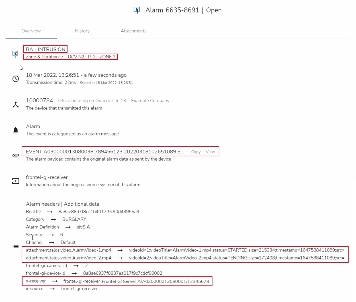
Alarms received through a Virtual Frontel GI Receiver can contain video clips from cameras connected to panels. The alarm example below demonstrates this particular case.
The figure below shows the Overview tab of an alarm:

The following details can be observed on the Overview tab (highlighted on the figure):
-
the alarm code field contains the evalink talos-interpreted (BA) and the original Frontel GI (INTRUSION) codes of the alarm / Frontel GI event
-
the Zone & Partition field provides panel-specific details:
- 7 - DCV N2 – the index and name of a device connected to the panel (in this particular case, the camera)
- 2 - ZONE 2 – the ID and name of the the area configured on the panel from which the alarm arrived
These details were obtained from the attributes of the Frontel GI event.
The devices and areas configured on a panel can be viewed in the Virtual Frontel GI Receiver instance on the [site] > Integrations page, while the alarm data transfer from the panel is in progress. For details on observing the panel configuration from evalink talos UI, see section Add Virtual Receivers on the Site Level > Panel Status View.
-
the alarm payload displays the original Frontel GI event string, as received from the Frontel GI server
-
the attachment fields display the links to video clips delivered with the alarm
-
the x-receiver field displays the string that can be used when referring to the particular panel in alarm expressions
Some alarm expression examples applicable to the Frontel GI integration are provided in section Use of Virtual Frontel GI Receiver.
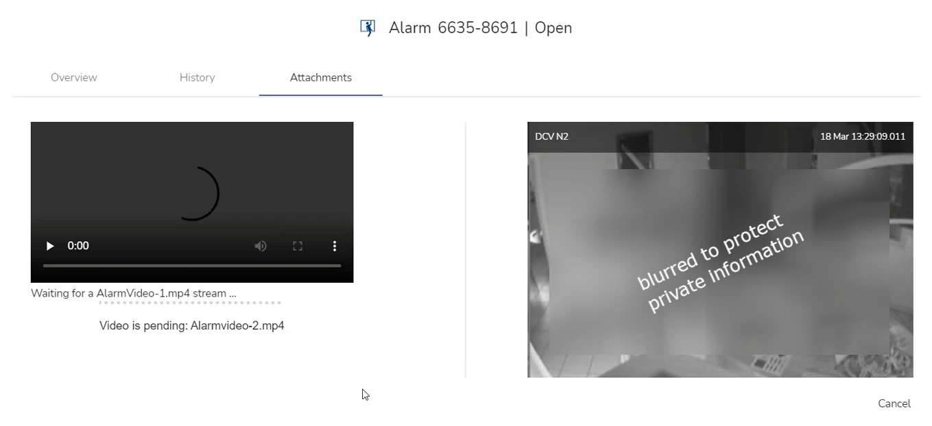
On the Attachments tab of the alarm, the attached video clips and their loading statuses are shown (see the figure below):

Beside video clips, live camera views can be provided with the alarm. Live camera views are available while the alarm data transfer to evalink talos is in progress.
Video data may take some time to load.
-
Video clips received by evalink talos through all video integrations, are stored in the event logs:
- in trial accounts – for 90 Days
- in regular evalink talos accounts – for 1,5 years
-
When a Frontel GI alarm is forwarded via Alarm Dispatcher, only attached video clips are forwarded with it. Live camera views are not available in forwarded alarms.
Supported Panel Models
Via Frontel GI integration, evalink talos can receive alarms from Resideo ® Videofied panels that communicate over Frontel GI protocol.
Examples of supported panel models are:
-
Resideo XTO-IP210 GPRS Control Panel
-
Resideo XL200 Alarm Panel
-
Resideo XL200GPRS Alarm Panel
-
Resideo XV-IP210 GPRS Control Panel
-
Resideo XT-IP210 GPRS Control Panel
-
Resideo XLL GPRS Alarm Panel XL200L
-
Resideo XTO-IP240 LTE-M Control Panel
-
Resideo XT-IP240 LTE-M Control Panel
-
Resideo WIP210 W Panel
-
Resideo W210 W Panel
-
Resideo WIP220 W Panel
-
Resideo WIP630 Cell + Ethernet W Panel
-
Resideo WIP620 Ethernet W Panel
-
Resideo WIP230 W Panel
 Link is copied