Virtual Receivers Setup on the Site Level
In this section, the term panel indicates a Resideo ® Videofied panel, if not stated otherwise.
Administrator or Manager can add one or multiple instances of Virtual Frontel GI Receivers on the site Integrations page (Sites > [site] > Receivers).
Each Virtual Frontel GI Receiver instance configured on a site listens to a separate panel that communicates with evalink talos through one of the Frontel GI servers (see section Work with Virtual Frontel GI Receiver > Virtual Frontel GI Receiver Basics).
There can be several Virtual Frontel GI Receiver instances configured on one site.
Different Frontel GI instances configured on the same site can receive data:
-
from the same Frontel GI server
OR
-
each from its own Frontel GI server
Work with Virtual Frontel GI Receiver Instances on Sites
Add a Virtual Receiver
Before you begin:
-
(optional, if there are several Frontel GI servers configured) find out which Frontel GI server you need to select for the panel
You need to know
-
which server the panel is connected to (can be requested from the panel installer or Administrator)
-
the name of the Connection Config that corresponds to this server in the global Virtual Frontel GI Receiver configuration (can be viewed by Administrator in the global settings of Virtual Frontel GI Receiver on the Company > Integrations page)
-
-
find out the details of the panel to be connected
-
the panel serial number
-
the length of the polling interval configured on the panel
A panel polls the Frontel GI server with its own heartbeat events, which are then forwarded to evalink talos.
- (optional) the panel account number
If the panel account number can be edited on the panel while connecting a panel to a site, finding out the account number can be skipped.
These values can be requested from the engineers who installed and configured the panel.
-
The figure below shows the creation of a Virtual Frontel GI Receiver instance on a site:
To add a Virtual Frontel GI Receiver instance to a site:
-
Go to Sites > [site] > Receivers > tab
-
On the Receivers tab, click on the Add a Virtual Receiver button and select Virtual Frontel GI Receiver from the list
-
In the configuration dialog that opens
a. In the Frontel GI Server field, select the name of the Connection Config that corresponds to the server in the global Virtual Frontel GI integration settings
b. In the Panel Serial Number field, enter the serial number of the panel (16 HEX characters)
c. In the Account Number field, enter the account number (4 to 9 digits)
infoThe panel account number can be configured on evalink talos side and set to the panel, or vice versa. The only requirement is that the account numbers on Virtual Frontel GI Receiver side and on the panel side are the same.
d. In the Supervision field, specify the length of the panel supervision period
The specified value should be greater than the interval at which the panel is configured to poll the server.
-
Click Submit to save the configuration
A new Virtual Frontel GI Receiver appears on the page.
If the respective Frontel GI server is connected, server connection status indicators in the record (see section Connection Status Indicators) are green. Panel connection status indicators will become green only after the panel sends the first alarm.
When the panel sends the first alarm to evalink talos, no 350 restore is triggered on any site in evalink talos.
Edit a Virtual Receiver
To edit a Virtual Frontel GI Receiver instance on a site:
-
On the [site] > Integrations page, go to the Frontel GI Receiver tab
-
In the appropriate Virtual Frontel GI Receiver record, click the Edit button
-
Edit the settings as desired and click Submit
Copy the Virtual Receiver Parameters
To copy the account number, click on Copy Account Number.
To copy the panel serial number, click on Copy Serial Number.
The number is copied to the clipboard.
Disable or Enable a Virtual Receiver
When a Virtual Frontel GI Receiver instance is disabled, it cannot receive alarms from the connected panel.
Disabling a Virtual Frontel GI Receiver is an option when you want to stop receiving alarms, but wish to preserve the configuration settings of the panel.
To disable or enable a Virtual Frontel GI Receiver instance on a site:
-
On the [site] > Integrations page, go to the Frontel GI Receiver tab
-
In the appropriate Virtual Frontel GI Receiver record, move the toggle in the upper-right part of the record
-
to disable a Virtual Frontel GI Receiver instance – to inactive position
-
to enable a Virtual Frontel GI Receiver instance – to active position
-
The figure below shows the disabling of a Virtual Frontel GI Receiver instance on a site:
If a Virtual Frontel GI Receiver instance is disabled after being operational for some time, some connection status indicators in the disabled Virtual Receiver may still display the ok status:
-
both server connection status icons can display [connected] and [supervision-ok] – if the Frontel GI server through which the panel was connected continues operating normally
-
panel connection status icons – the supervision status icon shows [supervision-ok] until the panel supervision period expires
For more information on status icons, see section Connection Status Indicators.
Delete a Virtual Receiver
To delete a Virtual Frontel GI Receiver instance from a site:
-
On the [site] > Integrations page, go to the Frontel GI Receiver tab
-
In the appropriate Virtual Frontel GI Receiver record, click on Delete Receiver on the lower-right
-
Enter the configuration code and click Confirm Delete
View Frontel GI Virtual Receiver Instance Details
Connection Status Indicators
Virtual Frontel GI uses indirect connection monitoring scheme (see section Work with Virtual Frontel GI Receiver > Virtual Frontel GI Receiver Basics). Therefore, instead of showing the Ethernet and Mobile transmission paths status (like most alarm transmitter integrations do), Virtual Frontel GI Receiver provides indications for server connection status and panel connection status (see the figure below).

The server connection and panel connection statuses show:
-
server connection – the status of the connection with the Frontel GI server through which the panel is connected
- icons or show if the TCP connection to the server is active
Persistent TCP connection is maintained between the server and evalink talos, see section Work with Virtual Frontel GI Receiver > Connection Details.
-
icons or show the supervision status – that is, if the latest heartbeat event from the server has arrived within the configured supervision period
The supervision period for the server is configured by Administrator on the global level (90 seconds by default).
-
panel connection – the status of the connection with the panel itself
-
icons or show if the panel is connected
-
icons or show if the latest event from the panel arrived within the specified supervision period
The supervision period for a panel is configurable by Administrator or Manager on the [site] > Integrations page, in the settings of the particular Virtual Frontel GI Receiver instance (1500 minutes by default).
-
Panel Connection Status
Normally, the panel connection status of a Virtual Frontel GI Receiver instance on a site is [disconnected], but this only means that the panel is not sending any data at the moment.
When the panel connects to the Frontel GI server to transfer an event (see section Work with Virtual Frontel GI Receiver > Interaction with the Panel), the panel connection status of the Virtual Receiver instance switches to [connected].
While the event data transfer is in progress:
-
the panel connection status remains [connected]
-
the Panel Status View (see section Panel Status View) is displayed in the Virtual Receiver instance on the site
-
live views of some cameras can be available in the details of the received alarm and in the Panel status view. These live views can be watched and refreshed
After the data transfer is over, and the panel disconnects from the Frontel GI server:
-
the panel connection status switches back to [disconnected]
-
the Panel Status View in the Virtual Receiver instance is hidden
-
live camera views in the alarm details stop being accessible
-
on the Alarms and Events pages (in the details of new and processed alarms)
-
on the Event Logs page (in the details of alarms and of workflows according to which these alarms were processed)
-
in the workflow processing view (if a Frontel GI alarm is opened for processing)
-
The video clips that arrived as attachments to the respective alarms remain accessible after the data transfer is finished.
Connection Statuses Interpretation
The figures below display a Virtual Frontel GI Receiver instance configured on the [site] > Integrations page.
This section explains how to interpret the connection statuses and understand when there's an emergency.
A Frontel GI server and a panel are connected, alarm data are being transferred
After a panel is connected successfully, the status of the panel connection indicators may not change at first.
After the first alarm arrives, the indications change as shown on the figure below:
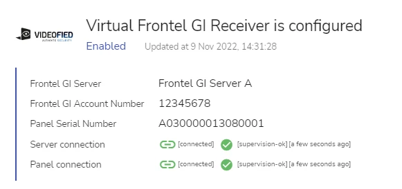
For explanations, see section Panel Connection Status.
The indications remain in this status until the data transfer is over and the panel disconnects from the Frontel GI server.
A Frontel GI server and a panel are connected, no data transfer is in progress
The statuses shown on the figure below is the most typical combination that can be observed for a Virtual Frontel GI Receiver instance.
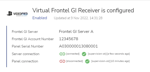
This state of a Virtual Frontel GI Receiver instance is normal and indicates no emergency.
A Frontel GI server is connected, a panel is not operating properly
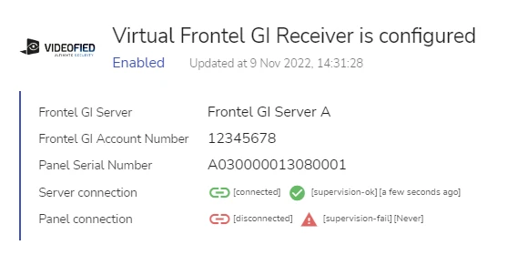
This state shows that the panel supervision period was exceeded. The supervision period is configured during the setup of the Virtual Frontel GI Receiver instance on a site, see section Add a Virtual Receiver.
This state of the Virtual Frontel GI Receiver is normal for a newly connected panel from which no alarms were received yet.
After the panel was once connected successfully, a [supervision-fail] status is abnormal. An indication near the [supervision-fail] status icon shows the time elapsed since the last event arrived from the panel.
When the supervision status of a panel switches to [supervision-fail], a CID 350 alarm is triggered on the site to which the panel is connected.
The reasons of a supervision failure can be as follows:
-
an incorrect supervision period was set for the Virtual Receiver instance
This setting is configurable by Administrator and Manager.
For details on configuring a supervision period, see section Add a Virtual Receiver.
-
an emergency – a panel malfunction or a network issue between the panel and the Frontel GI server
A Frontel GI server has disconnected
If a server is disconnected, the server connection status switches to [disconnected] almost immediately.
When a heartbeat event doesn't arrive within the specified supervision period:
-
the supervision status of the server switches to [supervision - fail] (see the figure below)
-
an alarm with a CID 350 code is triggered on the server supervision site (see section Work with Virtual Frontel GI Receiver > Supervision Sites)
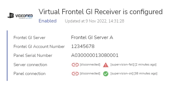
This state of Virtual Frontel GI Receiver is not normal and indicates an emergency on the Frontel GI server or a network failure.
After a Frontel GI server has disconnected, the alarm data transfer from the panel, if in progress, is stopped, and the panel connection status switches to [disconnected]. The server and panel supervision status icons remain [supervision-ok] until the corresponding supervision periods expire.
Panel Status View
While the alarm data transfer from the Frontel GI server is in progress, the Virtual Frontel GI Receiver record on the [site] > Integrations page is expanded to include a Panel status view.
The Panel status view displays the panel configuration, see an example on the figure below:
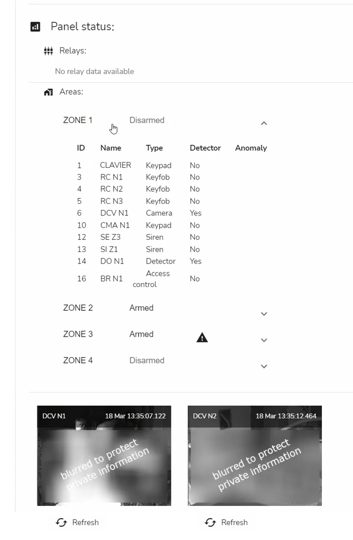
The following configuration details are displayed:
- the data from the relays configured on the panel
Remote management of relays is currently not supported for this integration.
-
the monitored areas configured on the panel and the devices / sensors connected to each area
In the example above, the configured areas have names ZONE 1, ZONE 2, ZONE 3, and ZONE 4.
Each area has:
- a status (Armed or Disarmed)
- a list of devices / sensors connected to it (for example, ZONE 1 has a connected a device DCV N1 with id 6 which is a Camera)
To view the list of devices connected to an area, click on the arrow to expand the area record.
-
live camera views from the cameras connected to all areas on the panel
You can switch between the camera pages using arrows.
After a panel finishes transferring the data and disconnects, the Panel Status view is hidden.
 Link is copied