Working with Virtual TNA Receiver Controls
View the Parameters and Connection Status of a Virtual TNA Receiver
You can view connection status for each Virtual TNA Receiver instance on your site. To access the receiver page, go to Sites > [site] > Integrations > TNA Receiver tab or Sites > [site] > Receivers > tab and select the receiver you want to view from the list.
A Virtual TNA Receiver instance displays the following data:
General parameters:
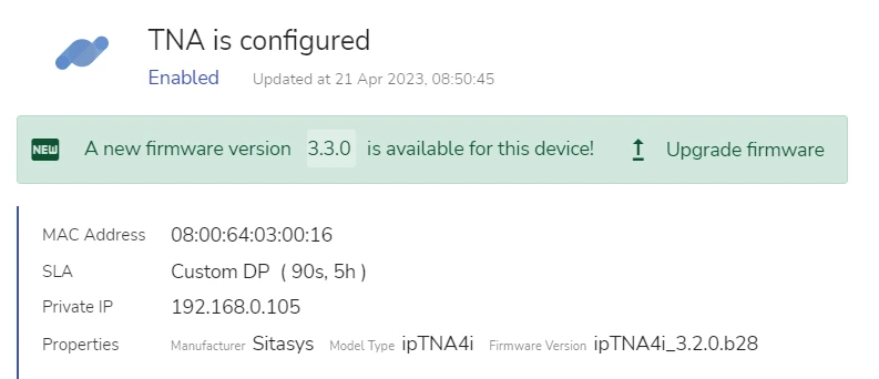
- The TNA panel MAC-Address
- SLA scheme used
- Private IP Address of the receiver
- General properties, such as Manufacturer, TNA panel model and firmware version
If there is a new firmware version available for your panel, evalink talos displays a message in the general parameters for your receiver instance.
Connection Status:

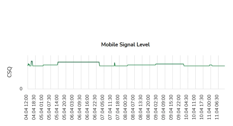
- Connection indicators
- Mobile signal level indicators
For details about connection status indicators, see section View Connection Status Indicators on the Virtual Receiver Page.
Working with TNA Input Components
On the Sites > [site] > Integrations > TNA Receiver tab or Sites > [site] > Receivers tab, evalink talos displays a consolidated data for each TNA panel and the corresponding Virtual TNA Receiver. You can view the same data with additional details and configure some additional settings on the TNA Web Server. For more details about the TNA Web Server, see section TNA Web Server.
The figure below illustrates TNA Input components:
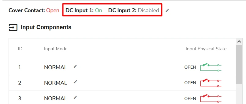
Each TNA panel has ten input components. You can extend the number of inputs with the use of an additional module. Each input can receive signals from a sensor or another monitoring panel connected to it.
evalink talos allows to monitor a separate status and edit the input mode for each input separately.
The following data is shown for the panel:
- Cover Contact (Open and in the state of Alarm or Closed and in the state of Restore)
This setting can only be changed on the TNA Web Server by users with an appropriate Access Level.
- Power Status for DC Input 1 and DC Input 2
The following data is shown for each input:
- Input ID Number
- Input Mode (Normal or Loop Supervision)
- Input Physical State (Opened or Closed)
The Input Components data block is available for an instance of the Virtual TNA Receiver only when the receiver is connected and active. If you disable the receiver or disconnect a panel from it, this data is not shown.
The indicators of the Input Physical State can be red or green, Open or Closed.
Red indicators mean the physical relay is switched to Off on the panel. Green indicators mean the physical relay is switched to On on the panel.
Open and Closed denote a particular Input's Alarming State. Open corresponds to Alarm and Closed corresponds to Restore.
Only Company Admins can edit Input Components. Managers and Operators can only view Input Components on evalink talos user interface.
All users, regardless of their User Role can also change Alarm / Restore settings for the TNA panel Input Components on the TNA Web Server, provided that they have an appropriate access level.
For more details about the TNA Web Server, see section TNA Web Server.
A link to details about working with TNA panel input components from the panel side will be added in the future evalink devices documentation releases.
Remote Access
Remote Access is one of the integrations available for your TNA panel. With an appropriate access level, you can enable or disable it on TNA Web Server. It allows access and troubleshooting of devices that are connected to the same network as your TNA panel from evalink talos or by evalink talos support team.
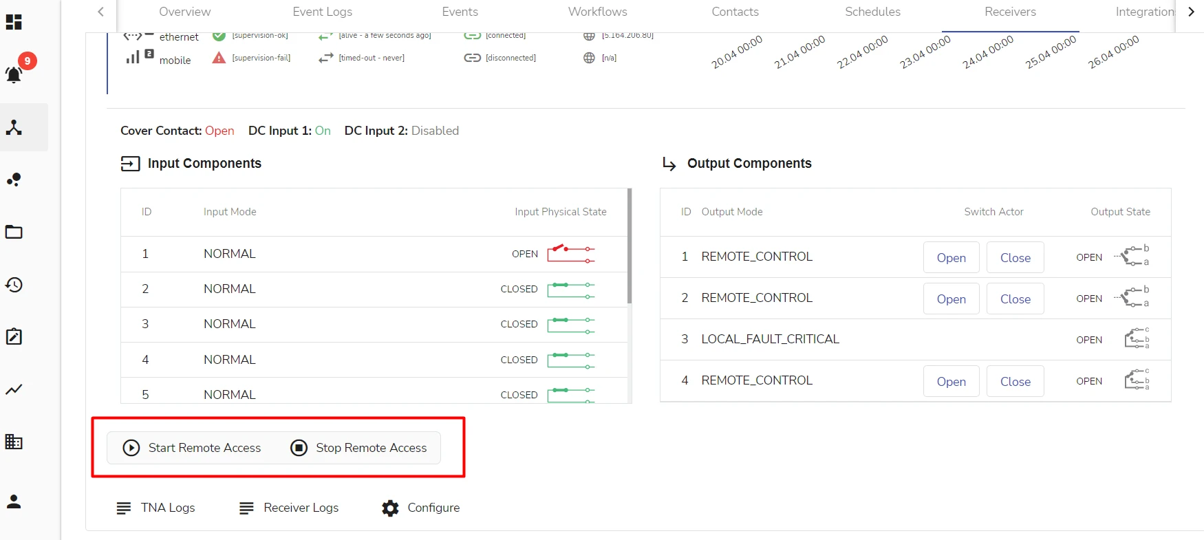
Remote Access controls are available regardless of whether this integration is enabled for your TNA or not. To be able to use Remote Access functions, you need to download and install a TNA evalink talos driver.
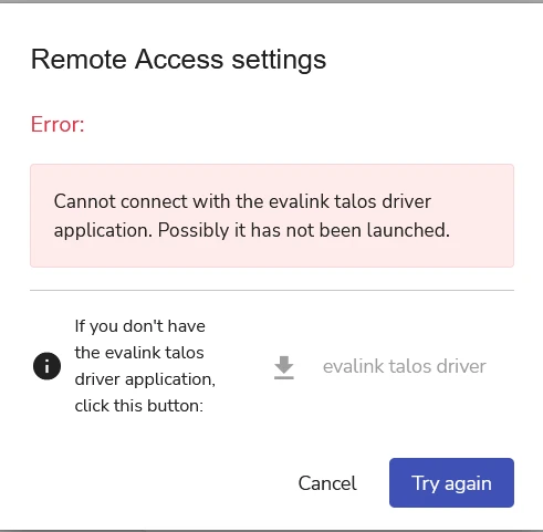
If you do not have a TNA evalink talos driver installed, you will be prompted to do so when you try to use the Start Remote Access control.
The figure below shows the dialog that prompts you to download the TNA evalink talos driver:
Details on how to use Remote Access will be available in the future evalink devices documentation releases.
Activate and Deactivate Power Sensors
When you use this option, you enable or disable power monitoring by evalink talos.
To activate either or both DC Input 1 and DC Input 2:
-
Click the Edit button above the Input Components data
The PowerSensors Activation dialog opens.
-
Activate or deactivate either or both power sensors as desired
-
Click Submit
When a power sensor is activated, the Input Component displays On status next to its record.
When a power sensor is deactivated, the Input Component displays Disabled status next to its record.
Edit Input Mode
You can configure Input Mode for each of the ten inputs separately. By default, all inputs are set to Normal Input Mode.
To edit the Input Mode:
-
Click the Edit button next to the input you want to configure
The Input Mode dialog opens for a corresponding input.
-
Select the necessary Input Mode from the dropdown list
-
Click Submit
The Input Mode is displayed for each corresponding input in the Input Components data block.
Working with Output Components
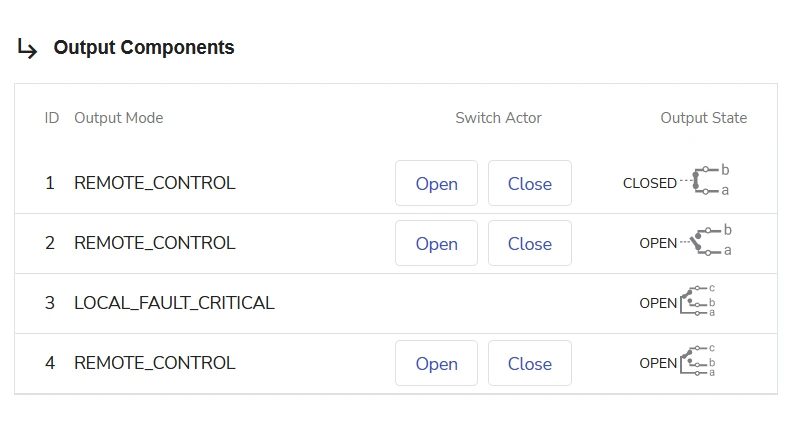
Each TNA panel has four outputs. You can extend this number with the use of an additional module. evalink talos monitors and displays data for each output and allows to send commands to it.
The figure below shows the Output Components for a Virtual TNA Receiver record:
The following data is shown for each output:
- Output ID Number
- Output Mode
This setting can only be changed on the TNA Web Server with an appropriate access level.
- Output State
- Available Output Actors
From the consolidated Virtual TNA Receiver record, you can use the Open and Close Actors for each output by clicking the corresponding Open and Close Actor buttons next to an output record. Depending on your choice, evalink talos displays the Output State for each individual output.
 Link is copied